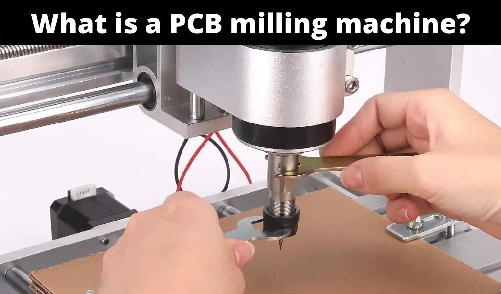
The fundamental function of a PCB milling machine (printed circuit board machine) is that it selectively mills away a layer of copper on the substrate material, typically a laminate board, to develop conductive areas, pads, structures, and traces on the board surface. They can also drill holes, but they are not plated so if you have a trace that needs to route on the top and bottom layer, you’ll have to stick a header pin in the hole and solder both sides to make the connection.
The PCB milling system consists of a single tool head which allows you to use different bits for what you need to do. This performs all actions that are required to develop a prototype board with the exception of via insertion and hole plating.
The software used in PBC milling machines is Computer Aided Manufacturing (CAM) software with Computer Numerical Control (CNC) which just means that the computer controls what the machine does. Typically, the company you are buying the mill from has its own software that you can use for free or a small cost. For example, Bantam Tools offers a free version of its Milling Machine Software for both Windows and MAC operating systems. Another company called Zippy Robotics has its own version of software called ProCAM which is used with their Prometheus Milling Machine.
PCB milling machines can be used to create prototypes and small production runs. They offer a number of advantages over traditional methods of PCB production, including faster turnaround times, lower costs for small production runs, and the ability to create complex circuit designs with high precision and accuracy.
PBC Milling Machine Specifications
A PCB milling machine is not one of the cheaper pieces of equipment for printed circuit boards. They typically range from $3000 – $10000. On the lower end of the spectrum, they will usually have a cheaper spindle with a high total indicated runout (TIR) which describes how much the bit wobbles as it spins about its axis of rotation. This can cause inaccurate trace widths or cause the bit to snap.
There are several types of PCB milling machines available, ranging from small desktop models to larger industrial machines. Some models are designed to be standalone devices, while others are designed to be used in conjunction with other machines, such as laser cutters or 3D printers, to create complete electronic devices. For example, the Snapmaker Artisan is a 3-in-1 machine that can do 3D printing, laser cutting/engraving, and CNC machining. You can use the CNC to mill your printed circuit boards.
When looking at PCB mills, you’ll see specs such as max speed, spindle speed, max PCB size, PCB type, minimum trace width/spacing, max drilled hole size, resolution, weight, connectivity, and power requirements.
Are PCB Milling and Chemical Etching Similar?
The PCB milling machine uses a subtractive process by carving out the traces and pads from a blank copper-clad board with the use of a high-speed spindle and an end mill. Therefore, there are no chemicals involved in creating the circuitry for your circuit board.
On the other hand, chemical etching uses chemicals to remove the copper that has not been protected by the hardened photoresist. This is a process where the board manufacturer transfers the circuitry images for each layer onto the board materials. Then, ultraviolet light or a laser is used to expose the photoresist which hardens to form a protective coating over the copper that should not be removed.
PCB milling machines are faster and more efficient than chemical etching, especially for small production runs or prototyping. Chemical etching can be time-consuming, and the process requires several steps, including the application of a resist, the exposure of the resist, and the etching of the board. In contrast, PCB milling machines can quickly produce a PCB design from a CAD file.
Overall, while both PCB milling machines and chemical etching can produce high-quality printed circuit boards, PCB milling machines offer several advantages over chemical etching, including precision, speed, efficiency, and environmental friendliness.
Advantages of Using a PCB Milling Machine
There are several advantages to using a PCB Milling Machine.
- No use of toxic chemicals for PCB production which makes it more environmentally friendly
- Save time and money by making prototype boards in-house as opposed to a board manufacturer
- Make one board as opposed to the minimum quantity (usually 4) required by most board manufacturers
- Much more efficient and simpler process compared to chemical etching
- Free software included with most machines
Limitations of Using a PCB Milling Machine
There are certain limitations on what can be accomplished with a PCB milling machine. The biggest limitation is that you can only create a board with two layers, the top and bottom. Another limitation is that you will not have solder mask or a silkscreen layer. Solder mask protects the exposed copper from shorts as well as from oxidation. Silkscreen is the layer for text and part outlines. You could etch the text in the copper, but it might not turn out as good.
The cost of the milling machine can be a costly investment if you are not making a lot of prototypes to offset the cost of doing it in-house versus sending the design files to a board manufacturer. Like we mentioned earlier, the price range for these machines is around $3000 – $10000. If it costs you an average of $20 to get a board manufactured by an outside vendor, you would need to make at least 150 boards in-house for you to pay the machine off and consider it a worthy investment.
Trace width is another limitation when using a PCB milling machine. The width of the traces on a PCB determines the amount of current that can flow through the circuit and can affect the overall performance of the circuit.
PCB milling machines are capable of producing traces with widths as small as 4mils, which is generally sufficient for most PCB designs. However, the trace width that can be achieved depends on the capabilities of the milling machine, the end mill being used, and the material being milled.
In some cases, achieving a specific trace width may require using a milling bit with a smaller diameter, which can increase the milling time and decrease the overall efficiency of the milling process. Additionally, if the trace widths are too small, they can become more susceptible to breakage or other defects during the milling process, which can impact the functionality of the circuit.
Conclusion
A PCB milling machine is a powerful tool for creating printed circuit boards with high precision and accuracy. These machines use a computer-controlled milling head to carve out a PCB design from a blank copper-clad board, offering several advantages over traditional methods of PCB production, including faster turnaround times, lower costs for small production runs, and the ability to create complex circuit designs. There are several types of PCB milling machines available, ranging from small desktop models to larger industrial machines, each with their own unique features and capabilities. With the increasing demand for electronics and the need for rapid prototyping, PCB milling machines have become an essential tool for engineers, makers, and hobbyists alike.