Printed Circuit Boards (PCBs) constitute the heart of electronic devices and appliances. The commands that make the device or appliance function are executed at the PCB. For this to happen, the circuit must be completed by connecting the components using the soldering process.
Soldering connects two components on a PCB by melting a filler metal known as solder to create a bond between the two points. As such, solder can be considered the glue that joins electric components on the board. Important to note that solder also refers to the process through which the filler metal is melted to create the connection.
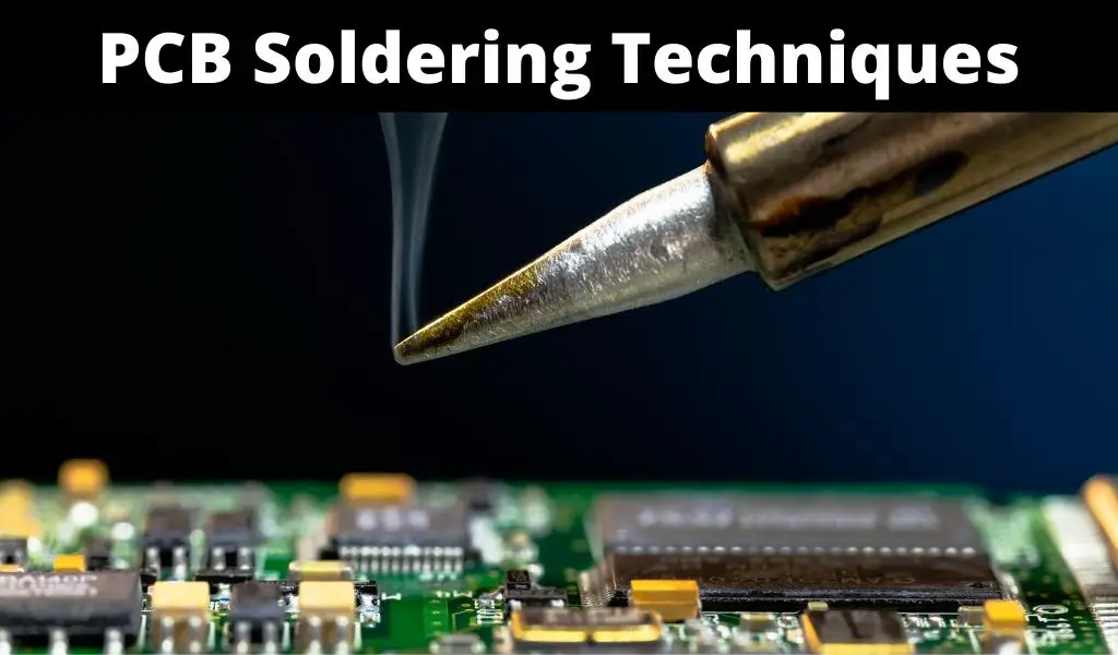
Solder has a lower boiling point than the metal parts they bond. For this reason, soldering entails heating the metal parts to be bonded using a soldering iron and placing the solder on the heated metal to melt it.
Solder that connects ends on a PCB board can be made of different materials. For a long time, tin and lead were used as a eutectic alloy (63% tin and 37% lead) or in a 60/40 combination. In recent times, safety guidelines and standards have directed the replacement of lead with other less toxic metals. These include Zinc, Silver, Cadmium, Aluminum, and Bismuth.
Soldering is a fundamental skill in the context of electronics. Because the optimum functioning of electronic devices and appliances relies on the soundness of a PCB, proper soldering is vital. This means expert PCB soldering techniques for maximum efficiency.
To better appreciate the techniques of soldering, it is important to understand the key steps in a simple PCB soldering task.
4 Quick Steps To PCB Soldering
Connecting the components of a circuit using soldering can be explained in these four simple steps:
Step 1: Assembling the materials
Soldering uses various tools and materials. They include:
The soldering iron: A pen or gun-shaped hand tool that is plugged into an AC outlet and is used to heat the two ends that are to be bonded with the solder. The soldering iron heats up to extremely high temperature to allow the two ends to be heated enough to melt the solder. The iron can carry between 15-30watts adjustable according to need. - The solder: is the metal alloy that is heated to create a bond between two ends and can be made of different materials as discussed in the previous section.
- The sponge: because heated solder easily sticks to the tip of the soldering iron, a sponge is an important material in the soldering process. It allows the electrician to clean the tip of the iron and ensure the consistent transmission of heat.
The soldering iron stand: serves as a holding device for the hot soldering iron preempting burning or accidental fires. - The third hand: a pair of crocodile clips that help the person soldering to hold the pieces being worked and avoid direct contact with heated pieces of metal.
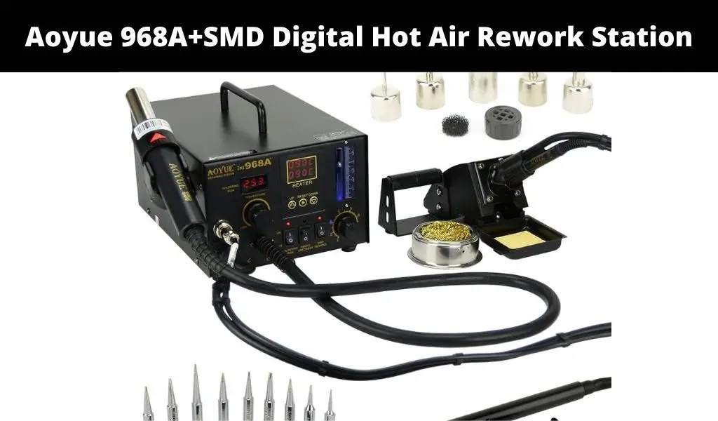
The soldering station: a kit with a built-in soldering iron and a constant power supply which controls the flow of power and allows you to keep your tools in one single place.
Step 2: Tinning
Tinning entails pre-coating the two ends being bonded with solder to make the bonding stronger and longer-lasting. It provides a smooth surface for the flow of molten solder, making the bond smoother and even.
Step 3: Soldering
Once the tips are prepared, the soldering iron is used to heat the tips which then melt the solder to create the bond. A good bond has a smooth cone shape and anything different requires cleaning by snipping off the excess solder or even removal and desoldering when the bond gives poor results. This should be done when the bond has cooled.
Step 4: Finishing
This could be considered as tidying up. It involves:
- Desoldering bad joints using a desoldering braid or wick before re-soldering it.
- Checking for shorts between adjacent joints, identifying cold joints or even poor-flow joints.
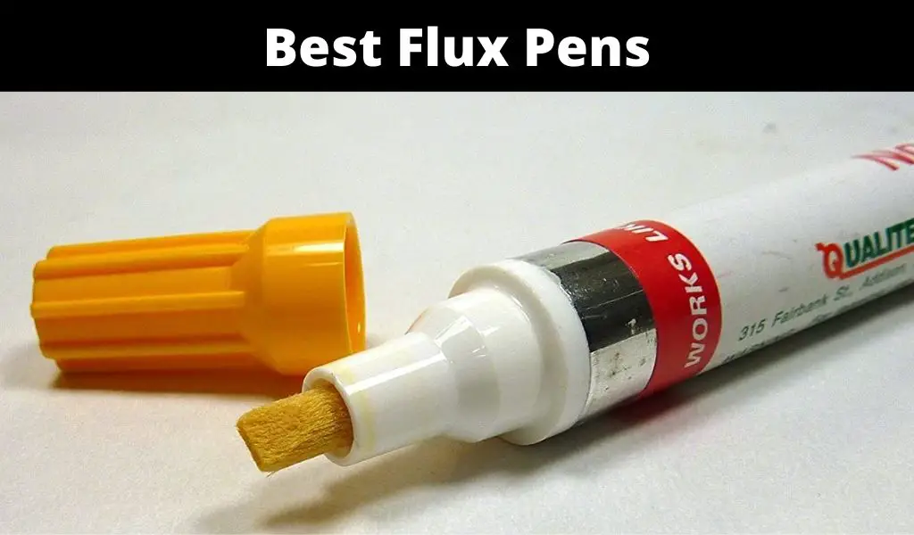
- Cleaning up by removing any residue flux and blowing the board with an air compressor.
With these steps in mind, it is easier to appreciate the various soldering techniques.
What are PCB soldering techniques?
Soldering techniques answer the ‘how’ question of the soldering process. While PCB soldering techniques can be taken to refer to what happens in each of the above steps of the soldering process, we are taking it to refer to the different methods used in the general process of soldering.
These methods are determined by the type of labor used (hand or machine) and the techniques employed in each of the machine-based soldering processes.
4 PCB Soldering Techniques You Need To Know
Here are four of the most common PCB soldering techniques:
Technique 1: Wave soldering
This technique is used in mass production. The through-hole components of the circuit are inserted through holes drilled on the PCBs. The process begins with arranging the boards on the soldering trolley and passing them over a flux-spraying section that cleans the components and copper tracks of any oxide deposits.
The trolley with the boards rolls over a preheating zone. Preheating preempts thermal shocks when the boards are eventually soldered with the molten solder waves. At the soldering section, a pump forms solder waves that solder the components as the boards pass over the molten solder.
Once the soldering is done, cleaning is done with solvents and deionize water to eliminate any flux residue. If the no-clean flux is used, then this step is skipped and the PCB is tested for quality. If the quality test is passed, the board is ready for use in the device or appliance where it is destined. A board that records a failed test is reworked to correct any errors
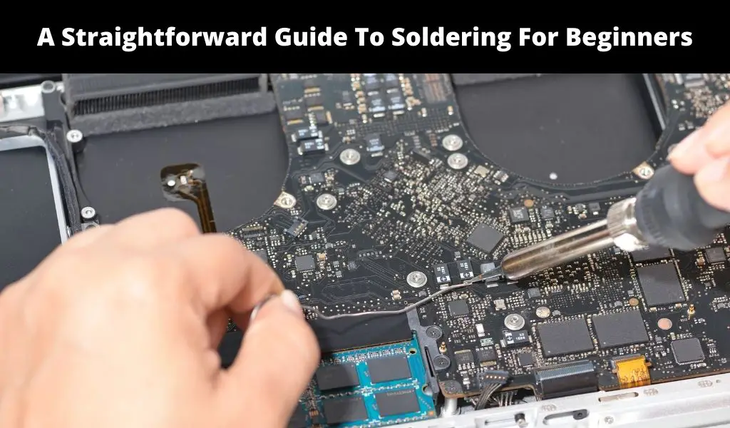
Technique 2: Hand soldering
To solder a single PCB, industrial processes like wave soldering may not be required. Hand soldering is also considered when soldering is done for purposes of repair or for small-sized boards that do not require a lot of work. The process uses the materials presented earlier (soldering iron, solder wire, alligator clips, soldering iron stand, sponge, and soldering station).
From a ‘how-to’ approach, the soldering process entails these quick steps:
- Place the board on a table or working bench and beside it the other material and tools that you’ll need for the soldering job.
- Plug the soldering iron and ensure it’s hot. Do not test with your fingers.
- With the soldering iron in one hand and the solder in the other, heat the metal ends to be joined and place the wire on the hot metal end so that it melts and flows to make the joint.
- Once the bond is created, remove the solder and the soldering iron and wait for the bond to cool.
- Once cool, remove any extra solder to leave the bond smooth.
- When all the joints are done and cooled, test for quality and make any needed repairs.
Technique 3: Reflow soldering
This technique is also used for mass PCB production to solder Surface Mount Device (SMD) components in Surface Mount Technology (SMT). The method uses a reflow oven, solder paste, reflow checker, and stencil printer.
During the reflow soldering process, the PCBs are passed in the first chamber known as the preheating zone. The boards are heated gradually to prevent damage when they move to the next zone known as the thermal soak zone. This zone exposes the boards to high temperatures to ensure that the components are at the required heat by the time they get to the reflow zone.
In the reflow zone, temperatures are increased above the melting point and the solder paste is melted into a liquid form to solder the components onto the boards. This explains why the reflow process is sometimes known as ‘time above liquidus’ or ‘time above reflow.’ Once soldering is complete, the boards are passed to the cooling zone to allow the solder to solidify on the joints.
Technique 4: Selective soldering
Selective soldering is the technique used to selectively solder electronic components on a board that is not completely assembled. A selective soldering machine is fed with a program that has the details of the job and the soldering is automatically done.
There are several options in this technique. One that refers back to the wave soldering process is known as the Selective Aperture Wave Soldering. In this option, the components of the board that don’t need soldering are covered with solder that can be easily peeled off, and the boards are passed through the wave soldering machine to solder the targeted components of the board.
The second option in selective soldering is Laser Selective Soldering. In this technique. A diode laser is used to solder components onto the board following a pre-programmed process that indicates where soldering should be done and where it should not.
In sum
When speaking about hand soldering, the steps used can be considered as the techniques in PCB soldering. However, there are several machine-aided soldering methods that could be read as variations of the PCB soldering process and techniques.